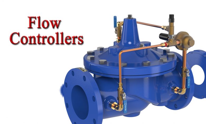
6 Types of Flow Controller that automatically control the Flow rate

The reason for having flow control is speed regulation. Besides this, the flow rate will decide the pace of energy transfer at a given pressure. The relation between the two is this: actuator force x distance = work of to load. Energy transfer has to be similar to work done. The actuator speed thus detects energy transfer. When such, speed changes according to the rate of flow.
When you would like complete information regarding industrial flow systems, see flow efficient for today’s information. Flow controllers are also primarily used in manufacturing to determine items on a conveyor belt. Or even used to control airspeed or quantify powder flowing through the air. The electric device looks at a sensor and closes the gates of valves in response to the signal input.
Below are the types of flow control:
Orifices
The orifice is an easy method to control flow. When controlling flow, the orifice with the pump will be in series. It may be as easy as a hole drilled in a fitting that is permanently fixed. Alternatively, it can be a needle valve that is calibrated, operating as the variable orifice. Each of these works as non-compensated valves.
Flow regulators
This valve is more complex compared to a fixed orifice. The orifice is used to sense the flow rate as pressure drops across the orifice. There is a piston that will compensate for variations in outlet with inlet pressures. The determined accuracy can be 5% or less with calibrated valves made around a dedicated flow rate point.
Bypass flow regulators
The flow in more of the set flow rate gets back to the tank through a bypass port. The flow rate is controlled in a throttling fluid across a certain orifice which is regulated by using a compensator piston. It is a basic efficient design, so that is the standard regulator.
Demand-compensated flow controls
In this setup, the liquid will be diverted to the primary circuit at a controlled flow rate. This liquid is mainly utilized for work in secondary courses using no effect of the primary circuit. The valve operates when flow to the main circuit is managed. Flow in the whole system closes when flow to the primary course is cut.
Pressure-compensated
This setup is covered with a seral orifice with a compensator, which is in series. The compensator will automatically increase the changing the inlet and load pressure. It assists in managing a constant flow rate to an accuracy of 3%-5%.
These valves have an integral reverse flow check valve that allows fluid to flow without restrictions in the opposite direction. Other than that, an integral overload relief valve can route fluid to a tank once maximum pressure is reached.
Pressure-compensated flow
As hydraulic oil viscosity varies with temperature, as when the clearance of the moving parts of the valve, the output of flow control valves may drift as temperature changes. This happens in conjunction with adjustment to the control orifice for development in pressure. To offset this problem, a temperature compensator will increase the openings of the control orifice to correct these effects of changes in viscosity because of the temperature variations.
Priority valve
In this setup, the flow control valve provides liquid at a set rate to the primary circuit. As like, it works similarly as compensated flow valves that are pressure-compensated. A flow that is more than what is needed in the primary circuit will be passed onto the auxiliary circuit at a lower pressure than the primary circuit.
Should the load or inlet pressure change, the major circuit prioritizes the secondary circuit supplying the flow rate.
Deceleration valves
This comes as a customized 2-way spring-counterbalance valve that is cam-actuated. It is helpful as it is used to decelerate a load being driven through the cylinder. A cam that is fixed to the load or cylinder will stop the valve gradually.
It gives a variable orifice that causes a slow rise in the cylinder’s back pressure when the valve stops. Some of these deceleration valves also feature pressure compensation.
Conclusion
Flow controllers may have multiple control modes or operate that may or may not use separate inputs with outputs. Specification for flow controllers is controller functions, number of channels, and type of output together with user interfaces.


